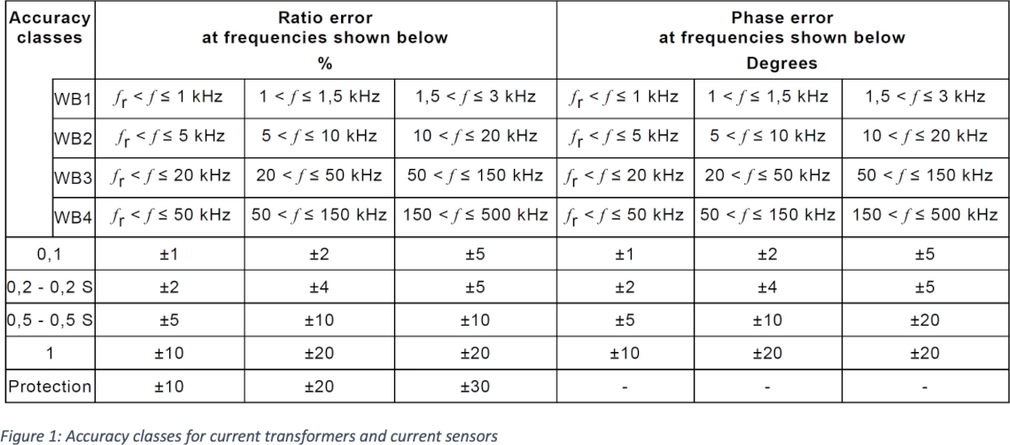
Many current transformers and current sensors are increasingly being tested and specified for their bandwidth. Standardization is also already defining accuracy classes for higher frequency components. The basis for the IEC61869 family was updated in 2023. The accuracy classes up to 150 kHz are mainly intended for power quality applications.
The range between 150 and 500 kHz are intended for travelling wave-based protection applications.
There are only a few laboratories that offer these accuracy tests. In general, the test setups are also not traceable to measurement reference systems in accordance with IEC 17025, meaning that only test laboratories with a good reputation should be selected.
Manufacturers and users can also carry out their own tests. However, standard equipment is not currently available on the market. The set-up should also be carefully considered in advance.
Gain phase measurement
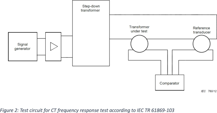
Initial assistance was already provided in 2012 with the technical report IEC TR 61869-103, where the first suitable test setups were published.
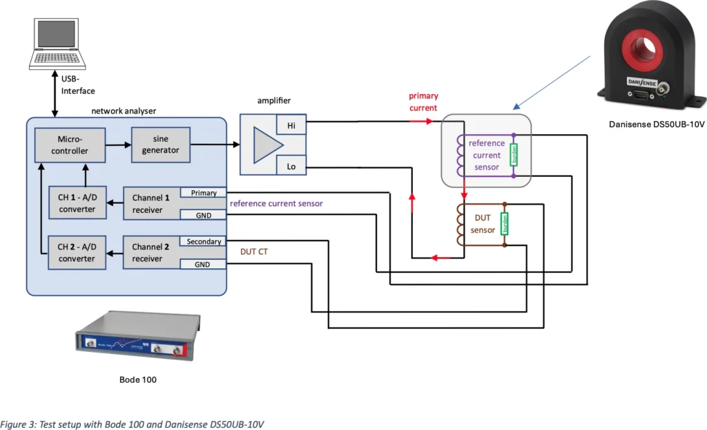
There are now also very well-equipped network analyzers that offer easy-to-use software for these tests. A frequency sweep with 800 or more measuring points can be performed in just a few seconds. An example of this is the Bode 100 from OMICRON Lab. The structure is shown schematically in the following illustration.
A Danisense fluxgate current transducer with an output voltage of 10 volts is recommended for the reference sensor. This output signal is also compatible with the Bode 100 input channels. In the Bode Analyzer Suite you can choose the transfer ratio for the reference sensor and the Device Under Test (DUT) easily.
Analyzing different waveforms
The output signal of the network analyzer is always a sinusoidal waveform.
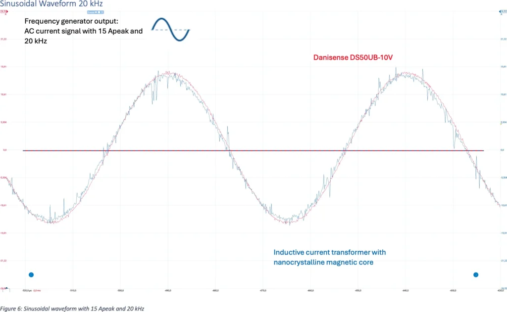
It is often also necessary to determine which signal forms the actual sensor can transfer. An oscilloscope is used for this purpose. The waveforms of the Danisense reference sensor and the test sensor are shown in the following.
Due to the electrical design and the aluminum housing, electromagnetic interference in the Danisense current sensor is significantly attenuated.
Sinusoidal Waveform 20 kHz
Sinusoidal waveform 50 kHz
Triangle waveform with 50 kHz
There are significant differences between the DS50UB-10V and the DUT.
Pulsed current with DC offset
Only the DC component is not transferred by the DUT. The AC component is transferred without saturation effects.