Home|Documentation|DR series – How to calculate the total measuring resistance
DR series – How to calculate the total measuring resistance
Introduction
The DR series is suitable for current values greater than 3000 A. A major difference to the smaller Danisense
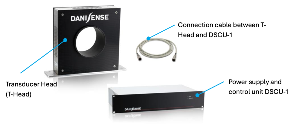
current transducers is that all electronics are installed in the supply unit. The transducer head consists only of various iron cores, copper windings and a housing.
For the variants with current output, it is necessary to take into account the length of the connection cable
between the transducer head and the supply unit when calculating the total measuring resistors.
The included standard cable is 5 m long. However, cable lengths in 5 m steps up to 30 m can also be ordered.
Datasheet specification
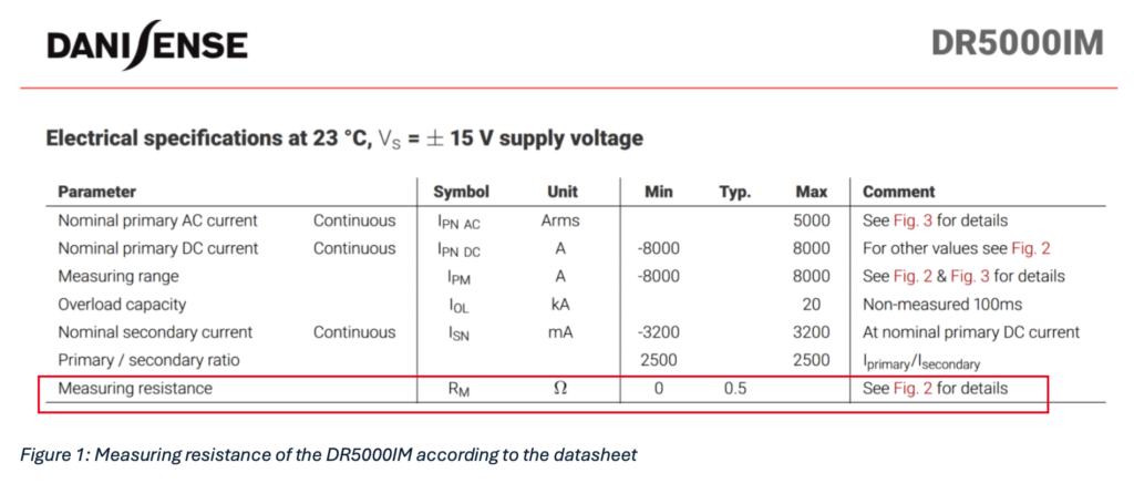
In the datasheet the measuring resistance is often specified as a typical value.
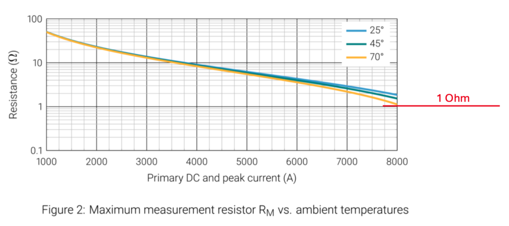
In the comment we can read that details are specified in figure 2. Figure 2 shows the maximum total measuring
resistance RM in relation to the current value as a DC or peak current in A.
It is obvious that larger measuring resistors can also be used if only small currents are to be measured. For
example, if a DC current of up to 8000 A is to be measured and the ambient temperature can reach up to 70°C,the
total measuring resistor must not exceed 1 ohm.
It should be noted that the resistance of the connection cable between the transducer head and the power
supply and control unit (DSCU-1) must also be taken into account.
The following figure specifies all partial resistance values and defines the final calculation formula.
The laboratory cables, which are not included, can be plugged into the corresponding sockets on the rear panel.
For EMC reasons, the laboratory cables should be twisted.