
Increasing fire security with the help of Residual Current Monitoring (RCM)
Introduction
Several studies in various European countries show that the most common causes of fires in and around buildings fall into two categories: electricity (30-35 %) and human error (15-20 %). Despite state-of-the-art electrical safety systems, there are always reports of building fires. The most common fault in the electrical supply system is a fault current that flows between the conductor and earth due to an insulation fault. This article looks at possible failure mechanisms in residual current monitoring and provides an overview.
Electrical circuits in buildings are protected by two diQerent circuit breakers.
- The overcurrent protection device, also known as an electrical fuse or Over Current Protection (OCP), interrupts an electrical circuit if the electrical current exceeds a specified current value for a specified time. There are various types of overcurrent protection devices such as fuses or circuit breakers. All electrical fuses in a house or flat are usually housed together with other circuit breakers in a distribution panel. Overcurrent devices protect cables or other equipment from damage caused by excessive heating, which would result from the overcurrent flowing over a longer period of time. An overcurrent can be caused by an overload or a short circuit. Overcurrent protection is mandatory in most countries in accordance with building regulations and standards for electrical installations.
- A Residual Current Device (RCD) is a life-saving device which is designed to prevent preventing people to get hurt in case of direct contact with live conductors, such as a bare wire. RCDs oQer a level of personal protection that ordinary fuses and circuit-breakers cannot provide. An RCD is a sensitive safety device that switches oQ electricity automatically if there is a fault. An RCD is designed to protect against the risks of electrocution and fire caused by earth faults. For example, if a person touches bare wires in a lamp in a bathroom and the wet floor has an electrical connection to the grounded radiators.
There have been important changes and developments in the field of RCDs in the last few years. Important innovations in this area are therefore described below. The correct selection of the already oQered devices can possibly minimize the risk of fire in the electrical system.
Principle of RCDs
The principle of RCDs is illustrated in the figure 1 below. If a person touches a non-insulated conductor, a part of the current can flow through the person, as the resistance of the human body is approx. 800 ohms. In many cases this resistance represents a rather low resistance to earth. This current flows via the earth back to the voltage source (transformer earthed secondary side). If the current does not flow back through the summation current transformer, a residual current occurs. If this value is high enough, the RCD trips and interrupts the entire circuit.
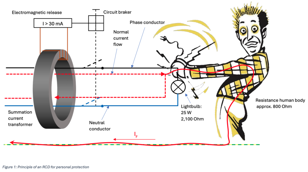
Tripping between 50 and 100 % of the rated residual current is specified in the international standard. If the 30 mA RCD trips, there must be a residual current of 15 to 30 mA. The threshold of 30 mA is intended to ensure personal protection, which is required wherever freely accessible sockets are available.
In the industrial environment, in addition to the administration buildings, which are protected with 30 mA RCDs, we usually find larger machines that are used for production. Even if these machines do not have any freely accessible sockets, protection using RCDs would also make sense. Insulation faults in the machines can also cause fires or malfunctions, which also represent a source of danger. There are diQerent RCDs on the market that have diQerent tripping values and therefore pursue diQerent protection purposes. There are three diQerent types of protection with their corresponding tripping currents which are listed in the following table.

A current that flows between the conductor and earth and emits at least 60 W as heat can cause a fire. At a supply voltage of 230 V, this corresponds to approximately 300 mA. RCDs for fire protection therefore have a maximum tripping value of 300 mA.
RCDs for di4erent signal waveforms
In addition to the current value, the signal form of the current is now also crucial for the correct functioning of the RCDs. Today, many electrical loads must be labelled as non-linear loads because these devices take a non-sinusoidal current from the mains. As a result, the residual current detected by the RCD often has a nonsinusoidal curve shape. To ensure that the RCD functions correctly, the connected loads must be taken into account with regard to the RCD to be used.

If, for example, a new washing machine is purchased and the manual specifies a type B personal circuit breaker (30 mA) and this is not taken into account, the following scenario may occur.
Due to a fault, the washing machine produces a direct current as a residual current of 8 mA. However, the individual circuits in a distribution cabinet are only protected by a type A RCD. A direct current is not specified for the type A RCD. A direct current of at least 6 mA has the eQect of pushing the small current transformer installed in the type A into magnetic saturation. The hairdryer then falls into the bathtub filled with water. Here, the diQerential current now flows via the bath water into the electrical earth and back to the earthed secondary winding of the transformer of the utility company. This residual current now has a pulsed or sinusoidal waveform that is actually covered by the type A RCD. If this residual current is now 40 mA, for example, the type A RCD should trip. In this case, however, the RCD does not trip because the iron core of the current transformer is already fully magnetized by the 8 mA DC current, so that the current transformer can no longer transform the 40 mA to the secondary side. If an RCD type B or B+ has been installed in the electrical distribution system, the RCD would certainly have tripped, as the residual current value has exceeded the tripping threshold with a value in total of 48 mA.
Machines and RCDs
If there are no freely accessible sockets in industrial systems, the operator is not obliged to protect the systems with an RCD. From a safety point of view, protection against residual current is always advisable. However, it is often the case that current peaks during the switch-on process of motors or other inductive equipment can lead to false tripping, which can have a harmful eQect on production processes.
There may also be system-related residual currents. High-frequency components in the current signal can flow to earth through filters or cable capacitances. In the following figure, these system-related residual currents are shown schematically using the example of a frequency converter.

These system-related residual currents can certainly reach levels so that protection with an RCD for fire security (300 mA) can no longer be used.
A residual current monitor can oQer a solution to this situation. The following figure 3 shows that, in contrast to the RCD, an RCM cannot independently interrupt the supply line. The residual current is only measured and outputted via a suitable interface. In addition, RCMs have one or more relay outputs, which in turn can be used to control circuit breakers.

Danisense solution
The Danisense RCM solutions have a relay output and a TRMS value which is transduced into a 4-20 mA DC standard machine signal which can be easily processed by a Programmable Logic Controller (PLC) or universal measurement device. For a deeper analysis an USB-Interface can be connected to a Laptop with the SRCM software tool. With this configuration it is possible to analyze the current signal in more detail. Among other things, the software oQers an oscilloscope view and an FFT analysis.

Residual current monitoring via the PLC
In complex industrial machines, a wide variety of electrical components form a system that is controlled via PLC. Accordingly, these plants may have higher residual current levels than in the above-mentioned tables. For example, the following values result from a production plant with a rated current of 235 A.

Even if continuous residual current monitoring can replace insulation testing due to international standardization, an analysis of the insulation resistance via the measured values shown above is not quite simple. In the plant, a wide variety of individual consumers are controlled, which in total generate diQerent residual current levels.
For this reason, some PLC manufacturers already oQer residual current sensors in their portfolio that can be connected to the PLC via machine standard signals. By linking the various machine statuses with the measured residual current levels directly after the start-up and the successful safety tests a “healthy” RC baseline can be saved in the PLC. With this data a reliable and meaningful monitoring of the production plant can be carried out.
Conclusion
In general, an RCM can be used as an early warning system, as many insulation faults lead to slowly increasing residual currents. For this reason, these devices are categorized as predictive maintenance measures. In many cases, an insulation test, which is part of the periodic safety inspection required by many supervisory authorities, can be avoided. RCM devices are already mandatory in properties that are part of the critical infrastructure, such as data centers and hospitals. Applications in the industry, where unforeseen machine failures are a problem, also benefit. RCM is the ultimate solution for improving safety and system availability in case of insulation faults.