How to choose Danisense current transducers and system interface units
Danisense Current Transducer, (sometimes referred to as DCCT) detects and accurately measures an electric current (primary or input current) passing through a conductor. It provides an analog output (or secondary) signal which is an exact representation of the primary current which can be DC, AC, high frequency or of any complex waveform. The output signal of a DCCT is available as a current or as a voltage. Just like conventional ACCT, the secondary signal of a current transducer is fully insulated against the primary current. It is used for control, protection, feedback, or monitoring purposes.
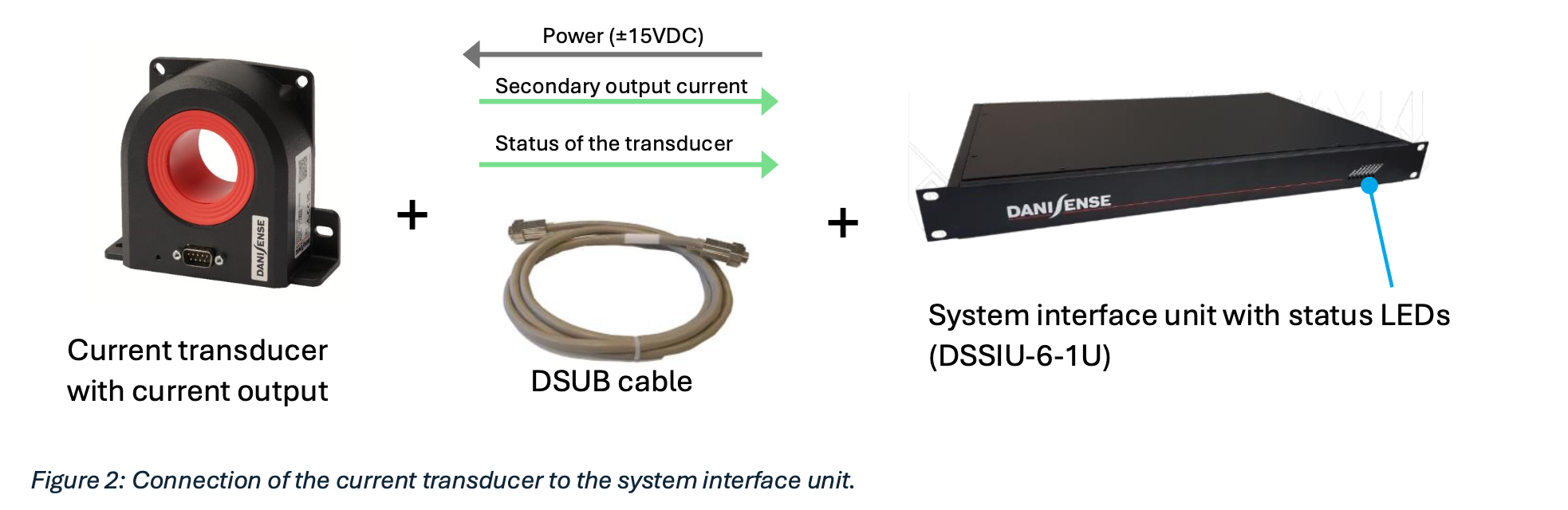
A DaniSense System Interface Unit (DSSIU) provides the required +/-15V power supplies to a DCCT and allows convenient accessibility to its output signal. In most general set-ups, DCCTs are located at the power circuits (such as machine room) whereas a Danisense system interface unitis placed in control room together with other measurement devices (oscilloscope, power analyzers etc.). Danisense offers different cable lengths, (DSUB cables) from 2m to 20m, to cover all your needs.
Besides, Danisense system interface units have many other useful features which will be introduced in this article.
To define the most suitable current transducers and system interface units for use with your measurement device, the first question to be asked is “What kind of input channels is available on the measurement device?” Current input? Voltage input?
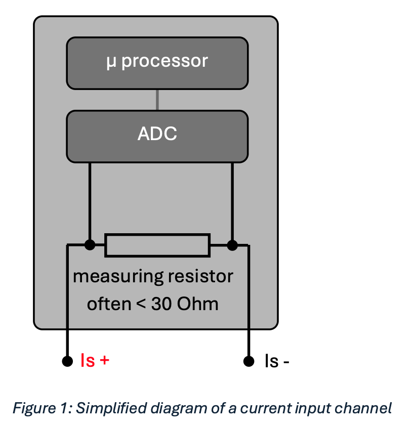
1. Current input channels
There are generally two variants. In the first variant, currents can be processed directly by the measurement device. There is a measuring resistor in the input channel. The current flows through the measuring resistor, causing a voltage drop across the resistor. This voltage is then transferred to the Analog Digital Converter ADC, which forwards the digital value to the microprocessor.
The values of the measuring resistance are often in the mOhm range to limit the amount of Joule heat loss and to avoid saturation of the current transducers.
Danisense offers a large portfolio of current transducers with current output. The DCCT secondary current is routed to the system interface unit via a DSUB cable (DE 9 version). In addition, the status signal of the current transducer is available at a DSUB25 connector located at the back panel, while the green LED of the current transducer is replicated at the front panel of the system interface unit.
At the back of the system interface unit, the secondary output current is available via two conventional banana jacks (4 mm female without shrouds). This allows the use of standard laboratory cables for connection to the respective measuring device.

In addition to the current output jacks, the system interface unit also offers 4 mm banana jacks (yellow) for connection to an external current calibration device. To enable this feature, however, the selected current transducer model must support the calibration option. The DM1200ID-CD3000 is an example of a current sensor with calibration capability. https://danisense.com/wp-content/uploads/DM1200ID-CD3000.pdf
In addition to the system interface unit DSSIU-6-1U for six current transducers, there are also other units for one or four sensors. These units do not have the option for connection to a current calibration device. The following table provides an overview of the available models with a current output.

It is important to ensure that the current transducer with current output is not overloaded with a resistance above the specified value. The typical measuring resistance is labelled as RM in the data sheet. Besides the resistance value in the input channel of the measuring device, the resistances of the cables have to be taken into account as well. The secondary output current flows through the pins 6 and 1.

If you use 115 V mains voltage instead of 230 V the maximum capacity is 4 DL2000ID / DL2000UB-1V
The following figure shows the scheme for calculating the total measuring resistance. The Danisense DSUB cables are designed in such a way that the voltage drop through the cable does not significantly reduce the required voltage directly at the current transducer.

The DSUB cables with lengths of 15 and 20 metres cannot be used with the DL2000. A sufficient power supply cannot be guaranteed for this current transducer. The voltage drop at these lengths is too big.
2. Voltage input channels
Some measuring devices require a voltage signal for the current measurement input. In these cases, current sensors with voltage output shall be used. Either the voltage signal is passed directly to the Analog Digital Converter (ADC), or the voltage is reduced by a divider and then passed on to the ADC. The input impedance of voltage inputs channel is in general very high, as only a very small current may flow through the parallel resistance of the measuring device. This is necessary to avoid affecting the voltage output signal of the current sensor. The input impedances are often between 0.1 and 10 MOhm.
Please consider that compared to current output devices, voltage output models are generally less immune to induced noises from external sources. In the following schematics, two possible configurations are shown.

1. Configuration
If the measuring device requires a voltage signal, a system interface unit with voltage output should be selected. There are two voltage output option available: 1V or 10V (at rated current). The shunt modules of the DSSIU-1-V and the DSSIU-6-1U-V are called Voltage Output Modules (VOMs). These modules consist of gain circuit and a high precision shunt resistor for conversion of the current output signal to a voltage signal.

The system interface units with this option are the DSSIU-1-V and the DSSIU-6-1U-V. The DSSIU-6-1U-V model has 6 channels for connection up to 6 current transducers simultaneously. Various Voltage Output Modules (VOMs) for different current ratings are available and can be factory mounted on any or on all of 6 channels of a DSSIU-6-1U-V.

Please note that the standard system interface unit DSSIU-6-1U (without the suffix V) is similar to the DSSIU-6- 1U-V but without the option for VOMs.
The table below provides a selection of Voltage Output Modules (VOMs) to be ordered with DSSIU-6-1U-V. Two nominal output voltage values, 1V and 10V are available.

With other current transducers, voltage values between 1 and 10 volts can also be generated. An overview can be found in the datasheet of the DSSIU-6-1U-V.
The one channel unit DSSIU-1-V with the available VOMs can be found here.
The gain circuits in the voltage output module are designed ensuring that the total measuring resistance RM of the current transducer is not exceeded.
For convenience, interface system unit with current outputs DSSIU-6-1U is equipped with banana jacks for the current output signal. However, as voltage signal is more prone to external noises, model DSSIU-6-1U-V is equipped with XLRmini socket to allow the use of a shielded cable. The XLRmini/Banana shielded cable is offered in option which allows connection of the output signal to standard measuring devices.

Each of the 6 channels on the DSSIU-6-1U-V can be ordered with or without VOM. If you do not specify a VOM for one or more channels, the channel is configured as a current channel. In this case, the current output signal from the current sensor is routed directly to the XLRmini socket. In this case, please select the XLR/Banana current cable.

The following figure shows an example of the rear side of the system interface unit DSSIU-6-1U-V where channels 1, 3 and 5 are configured with voltage output modules (VOMs) and channel 2, 4 and 6 are with standard current output. The stickers on the respective outputs provide detailed information on the configuration of the voltage outputs.

Retrofitting the current output models with voltage output modules is only possible at our factory in Taastrup (Denmark). This is to ensure the specified accuracy of the current transducers. In the example above the current transducer DL2000ID is selected.
As shown in the datasheet of the DL2000ID, the nominal secondary current is 1.333 A at nominal primary AC current (2000 Arms), which corresponds to a transfer ratio of 1500:1. However, by using the VOM 10V/ 1.333A, the new ratio which can be used for the measurement device is:

2. Configuration
In addition to the configuration described, Danisense also offers current transducers with voltage output. The voltage signal is provided via a BNC socket mounted on the housing. The DSUB cable between the current transducer and the DSSIU-6-1U only ensures the power supply of the current transducer. No shunt must be inserted in the secondary circuit. The circuit must be operated open. Otherwise, the voltage output signal will be negatively affected. The connection diagram is shown in the following figure 12.

In some cases, this configuration has a disadvantage. Voltage output transmitted through the BNC cable is to a certain extent influenced by external noises, especially when a long cable is used.
3. Current measurements without system interface units
In principle, the user can also use the already existing laboratory power supply unit. For his convenience, Danisense offers two different DSUB cables for connection between the power supply unit and the current transducer.
Type one is for current transducers with voltage output. An internal circuit converts the internal secondary current into a voltage accessible via a female BNC connector located on the housing.

The secondary output signal is only available via the BNC connector. No secondary current signal is available via the DSUB connection.
The four banana jacks are defined as follows:
1. +15 VDC
2. -15 VDC
3. GND (Ground)
4. Shield
Type two is for conventional current transducers with current output. Beside the four banana jacks as described in type one, two additional jacks Is+ and Is- are provided for the output current.

The six banana jacks are defined as follows:
1. +15 VDC
2. -15 VDC
3. GND (Ground)
4. Is+
5. Is6. Shield
Both cables have a length of 3 metres.
The standard values of rated secondary currents of Danisense current transducers vary between 100 and 1333.33 mA depending on the model ( https://danisense.com/products/ ). The measuring resistance in the input channel of the measurement device must not exceed the RM value specified in Danisense datasheet.