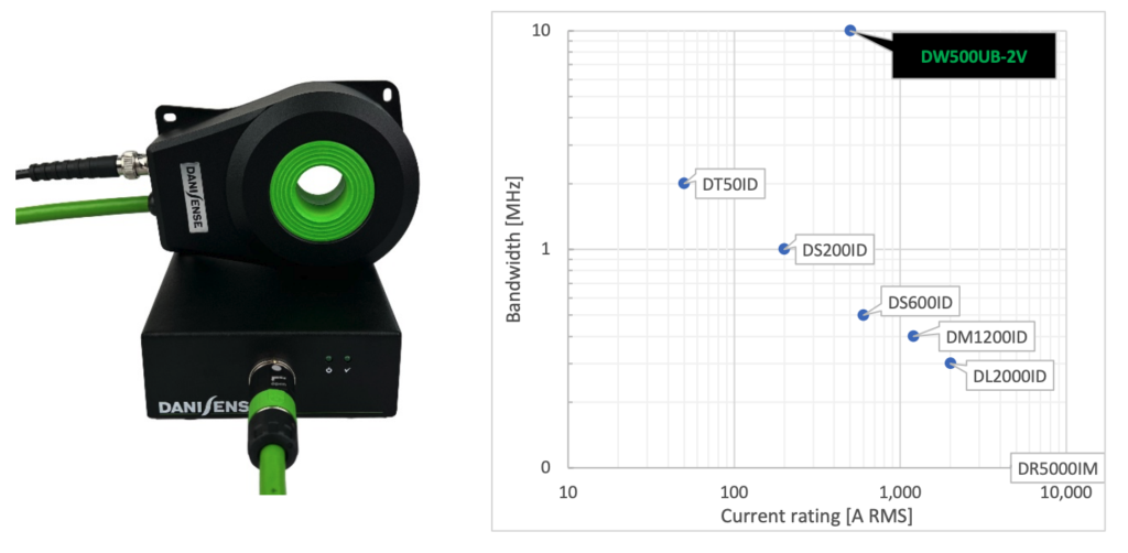
Wide bandwidth DW500UB-2V for power analysis
Introduction
Power conversion products based on wide bandgap semiconductor technologies such as gallium nitride (GaN) and silicon carbide (SiC) are now operating at significantly higher switching frequencies which can generate almost perfect sinusoidal waveforms. Filter elements such as chokes and capacitors can be made smaller and lighter because the inductance values of the chokes and the capacitances of the capacitors are inversely proportional to the switching frequency. In the future, SiC- and GaN-based components will continue to gain acceptance in more applications. Danisense introduce the new model DW500UB-2V with the capability to handle the wide bandwidths now required.
Background power analyzers
Power analyzers usually use the following basic formula for active power calculation.
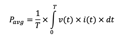
Thus, the digitized instantaneous values of the voltage v(t) and the current i(t) are multiplied together and the results are summed up over a defined time window. Basically, DC components, all harmonic and non-harmonic components up to the bandwidth limit or filter cut-off frequency of the power analyzer are taken into account. Power analyzers in the premium segment already operate up to a frequency of 10 MHz. In most cases, the voltage signal is processed directly by the power analyzer so that the complete bandwidth of the power analyzer can be used.
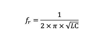
For current measurements of greater than 30 A, galvanically isolated current transducers are often used, which must transmit the primary signal to the secondary side with high accuracy. These current sensors have a copper wire winding and an iron core as their main components. Also, Rogowski coils consist of a coil body wound with copper wire. This construction results in a winding inductance and also unwanted capacitances that are always formed between the individual windings and between the individual winding layers. Accordingly, each copper wire winding represents a potential oscillating circuit. With Thomson’s oscillation equation it is possible to calculate the resonant frequency.
This means that current transducers often have a limited bandwidth. Internal filters in the Power Analyzer are activated to reduce the bandwidth for the power calculation accordingly. Otherwise, higher frequency components in the power analysis are sometimes strongly distorted by the current transducer, as the following figure 1 illustrates.
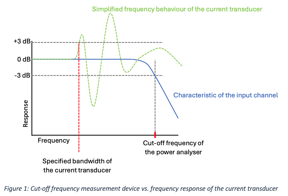
Compensation of these chaotic-looking error curves in the measurement device can only be performed to a limited level, as the oscillation characteristics are strongly dependent on the capacitance of the copper winding, so that the curves are shifted with temperature variations.
High switching frequencies in next generation power electronics
Especially when using frequency converters with a high switching frequency to control motors, active components of the power can also be found in the three-digit kHz range, since multiples of the switching frequency show up in the current and voltage signal according to the following equation.

The switching frequency and its harmonics consist of active and reactive power components. In order to measure these components with sufficient accuracy, the phase error must be highly accurate in addition to the amplitude error.
Phase displacement
Especially when inductive loads such as motors are used, the inductive component of the load increases with the frequency. The power factor decreases accordingly with increasing frequency. This in turn leads to an increasing influence of the phase error on the power calculation. This correlation is shown in figure 3.

The same phase error leads to higher error in the active power calculation (red colored). More precise values for different phase errors can be found in the following figure 4.

DW500UB-2V
The DW500UB-2V has no resonance interference up to 10 MHz. This is a basic requirement for linear transmission behavior up to 10 MHz. The phase error consists of a fixed time delay which is mainly caused by a 2 m coaxial cable. This time delay is mentioned in the test protocol. If the measurement device can compensate a fixed time delay the phase error can be significantly reduced. This is illustrated in the following figure 5.

In the selection menu of the LMG671 from ZES ZIMMER, for example, there is a corresponding input template in which the time delay can be entered.

In addition to accuracy, the current carrying capacity at higher frequencies must be considered not only for the primary conductor. The current transducer with its copper windings must also be designed accordingly. The DW500UB-2V can handle the whole nominal current up to 100 kHz at 25°C. The complete specification is mentioned in the datasheet, which is available on https://danisense.com/.