Interference signals and countermeasures
1 Overview
Interference voltages and interference currents can arise within a measuring system or be transferred into it from outside. The general mechanism is illustrated in the following figure.
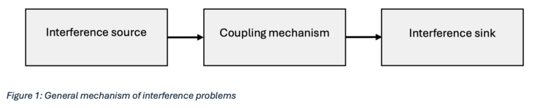
Due to their wide-spread range, connecting cables and cable systems in particular are often subject to sources of interference or exposed to interference.
Coupling mechanisms describe the way in which disturbance variables are transferred from an interference source to an interference sink. The following diagram illustrates the possible coupling mechanisms.
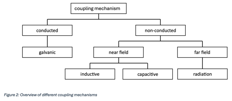
A basic distinction is made between conducted and non-conducted coupling mechanisms. While conducted interference occurs within shared circuits, a field-bound interference also occurs between galvanically isolated systems.
2 Conducted coupling
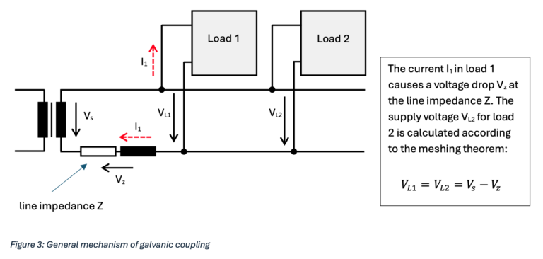
2.1 Galvanic coupling
Galvanic coupling occurs in circuits with common voltage sources and common conductor traces or common wires.
3 Non-conducted coupling
3.1 Inductive coupling
Figure 4 shows how inductive interference occurs: If the measuring line is passed through by a time-varying magnetic flux, which may originate from a neighboring high-voltage line, for example, a voltage is induced in the measuring line, which then appears in series with the measured voltage Vm. Due to the induced voltage, currents flow through the measuring line. These also flow through the input impedance of a measuring amplifier, distorting the actual measured voltage by a superimposed interference voltage. Such inductive interference can be greatly reduced by twisting the measuring line. The induced voltages cancel each other out in sections. Of course, the distance between high-voltage cables and measuring cables should always be kept as large as possible. As a rule, the measuring cable should be at least 1 m away from high-voltage cables. Likewise, the forward and return conductors should be combined on the high-voltage side in order to keep disruptive magnetic stray fields as small as possible from the outset. If the distances are insufficient and cannot be increased further, measuring cables or measuring transducers can be magnetically shielded by encasing them in highly permeable metal sheets. High-frequency magnetic fields can already be shielded by non-magnetic conductor materials such as aluminum.
Inductive coupling between a high-voltage line and a measuring line.

In twisted cables, the voltages induced by the interfering magnetic field cancel each other out in sections.

The following relationships take effect in principle.
- The induced voltage in the measuring circuit becomes greater if the rate of change of the current is faster.
- The induced voltage in the measuring circuit becomes greater if the coupling inductance between the conductor and the affected measuring circuit is higher.
3.2 Capacitive Coupling
The interference variable of capacitive coupling is electrical voltage.
Capacitive coupling occurs between two neighboring conductors with different potentials, such as high-voltage and signal conductors. In the broadest sense, the conductors represent the plates of a capacitor.
The electric field causes charges to be transferred from one circuit to another via these parasitic coupling capacitances. The coupling capacitance is directly proportional to the length of the parallel high-voltage and signal lines. It decreases as the distance between the conductors increases.

The magnitude of the coupled fault voltage in the system of v₂ is greater
- the greater the rate of change of voltage
- and the greater the coupling capacitance between conductors 1 and 2 .
The following figure 6 illustrates the formation of capacitive interference via cable stray capacitances. The interference current flows through the internal resistance of the measuring voltage source and causes a voltage drop, which then becomes effective in series with the measuring voltage . Capacitive interference can therefore be kept low if the internal resistance of the measuring voltage source is low and the distance between the high-voltage and measuring lines is as large as possible (usually at least 1 m). If the measuring voltage source is floating (or earth-symmetrical with an earthed center point), twisting the measuring line and earth symmetry, i.e. equal leakage resistances and between the two measuring conductors and earth, can ensure that both conductors carry the same interference voltage to earth (figure 6-B). The interference then appears as a 'common mode voltage' on both conductors, while the measurement signal appears as a 'differential voltage' between the conductors. If a differential amplifier is then used, almost only the measurement signal is picked up and the interference signal is suppressed. It is even more effective, as shown in Figure 6-C, to provide the measuring line and, as far as possible and necessary, also the measuring voltage source and the measuring amplifier with a grounded shield. In this case, capacitively induced interference currents flow off via the shield without even reaching the measuring conductors. The shielding material only needs to be highly conductive; ferromagnetic properties are not required.
A. Capacitive coupling between a power line and a measuring line

B. If the measuring signal source is floating, twisting and earth symmetry(𝑹𝑬𝟏 = 𝑹𝑬𝟐 ) can be used to ensure that no differential interference voltage occurs.

C. A grounded shield keeps interference away from the measuring cable.

The possible countermeasures are summarized here.
- Maximizing the distance between the two conductors
- Close installation of the cable to the ground structure
- Shielded cable, insertion of static shields (ground connection)
- Separating sensitive and interfering circuits from each other
3.2.1 Danisense measures to avoid interference problems
3.2.1.1 DQ, DS, DL, DM, DL Series:
The housing of the current transducer is made of aluminum and thus offers protection against unwanted higher frequency interferences. If the current transducer is connected to a DaniSense System Interface Unit (DSSIU) with a Danisense DSUB cable, the housing and the cable shield are electrically connected to the earth of the supply network.

Please make sure that the laboratory cables from the DSSIU to the measurement device are twisted and do not provide a big loop.
3.2.1.2 DT Series:
The housing is made of plastic and aluminum. The transducer head is enveloped in a copper foil, which is also connected to the cable shield of the DSUB cable via the DSUB connection. The cable shield is connected to the network earth via the DSSIU.
3.2.1.3 DR Series:
The transducer head is enveloped in a copper foil which is connected to the cable shield. The cable shield is connected to the earth of the supply network inside the electronics control box.
Sometimes a direct earthing of the aluminum housing can help as well but here you have to be careful with ground loops. Further assistance is available in the manual on page 18.
3.3 Radiation
Nowadays, non-linear loads such as switching power supplies not only cause harmonic distortions in the power grid but are often also responsible for electromagnetic radiation. For example, magnetic stray fields are generated by winding components and electrical stray fields by conductors with high pulse voltages. These fields can couple into the current transducer. Oscilloscopes can be used to record these oscillations. A conventional probe can be used to make this stray radiation visible. The probe tip is connected to the grounding adapter.

This radiation can, for example, pass through the inner hole of the current transducer and can therefore be recognized in the secondary signal.

An oscillation at approx. 3.33 MHz can be seen in the image above. The current transducers do not have a lowpass filter at the output, so that these signals are generally not attenuated. For oscilloscope applications, it is recommended to use oscilloscopes that can filter the input signal so that high-frequency interference is minimized.
Another example is shown in figure 10. With a DS50UB-10V without a power supply connected and an unearthed housing, an oscillation of approx. 44 MHz can be detected via the BNC connection. This oscillation corresponds to a primary current of approx. 20 mA peak to peak. The measurement was carried out on a standard home office desk.

The interference is outside the specified bandwidth of the current transformer of 500 kHz. A low pass filter in the single-digit MHz range could significantly reduce this interference.
3.3.1 Additional shielding against interference
It should be noted that metallic shields only show good attenuation properties at higher frequencies of electromagnetic radiation. The following figure shows the attenuation properties of a cylinder with a diameter of 20 mm and a wall thickness of 0.5 mm with different materials.

At low frequencies, high permeability of the material is highly recommended. The following table gives an overview of the properties of shielding materials depending on different field types.

Not all fields can be shielded by aluminum housing or copper foil. Undesirable fields can also occur in the cable entry for the primary conductor of the current transducer and thus induce a magnetic flux in the respective iron core of the current transducer. For these reasons, the current transducers are housed in an additional grounded metal box in some measurement setups. Identified sources of interference in the close range of the current measurements could also be shielded using appropriate shielding foils. Electrically and magnetically conductive foils are now available that can shield a wide range of potential interference signals.2
4 Noise
When measuring small signals in particular, it becomes apparent that electronic noise occurs in all circuits containing ohmic resistors or electronic components such as transistors.

The two most important types are thermal and shot noise.
4.1 Thermal noise
A metallic conductor or resistor contains a number of free electrons. The thermal motion causes collisions between the free charge carriers and the atoms, resulting in a constant exchange of energy. This also explains the resistance properties of the conductor. Since no current flows in an open circuit, the random movement of electrons in the conductor causes voltage fluctuations along the conductor, which leads to noise voltage at its terminals.
Thermal or resistance noise, also known as Johnson or Nyquist noise, is proportional to the temperature and the resistance value. The proportionality constant is the Boltzmann constant k. It indicates how much average thermal energy per Kelvin is supplied to a charge carrier. Thermal noise is independent of frequency, but increases with increasing bandwidth. The noise is often described by the power spectral density PSD (power spectral density) or noise power in the unit W / Hz. The effective values must be used for all calculations.
4.2 Shot noise
Electrical shot noise always occurs when an electrical current has to overcome a potential barrier. Shot noise arises because the total current flow is composed of the movement of individual charge carriers (electrons or holes) and each charge carrier crosses this barrier individually. This does not happen uniformly, but is a stochastic process. Overall, certain fluctuations in the current flow can also be observed at the macroscopic level
The magnitude of shot noise depends on the magnitude of the current flowing and shows no direct dependence on temperature. This distinguishes it from thermal noise.
Danisense uses components that are already characterized as low-noise components. When selecting measuring devices, ensure that the signal-to-noise ratio is high enough to obtain the desired measurement results.

It can also make sense to limit the bandwidth of the input channels of the measurement device.
Notes
1 Hans Albrecht Worlfsperger: Elektromagnetische Schirmung: Theorie und Praxisbeispiele (VDI-Buch) Gebundene Ausgabe – 25. April 2008